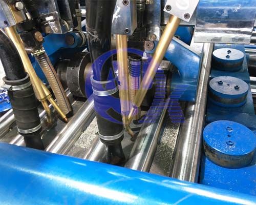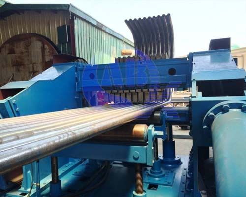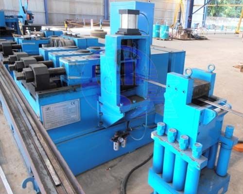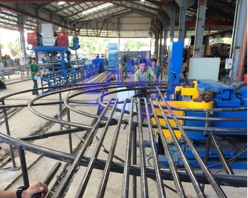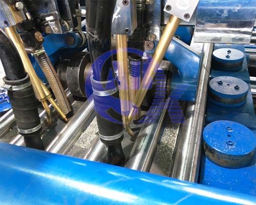
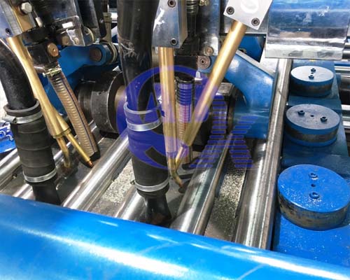
The standard membrane panel welder is designed to a width of 1600mm operating with 4 welding torches utilising submerged arc welding (SAW) technology. This is the most commonly ordered specification for good reasons:
- High productivity/efficiency in fabrication
- Panel products within transportation limits
- Practical and stable application
- Lower cost of machine and meeting sufficiency
We may however custom built to the customer's requirement (owing to technical limitations). Our experiences span from panel welders with varying widths, number of welding heads , SAW or MIG/MAG or both utilizing your preferred power sources.
ABK continues today to innovate and adopt newer technology in achieving user friendliness with the introduction of digital touch screen panels. The panel welder will greatly increase outputs and reduce overheads with just 1 operator.
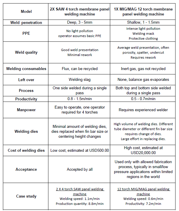
Comparison Table between SAW and MIG/MAG we hope would help you better decide on your investment
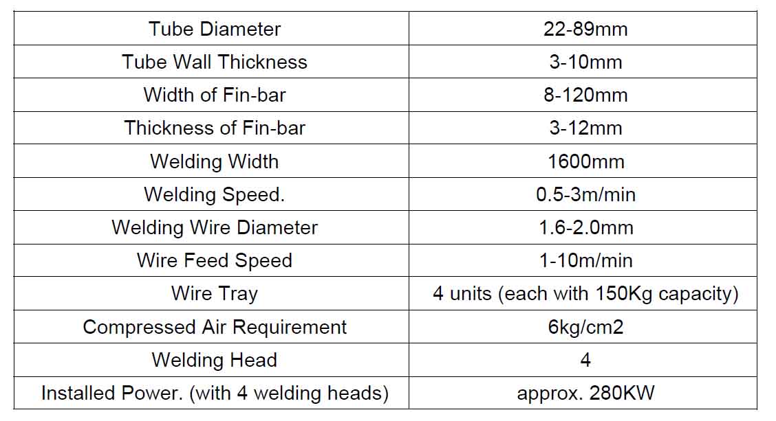
Overview of Specification
Membrane Panel Welding System
A basic membrane panel production line consists of 4 basic equipment. They are:
- Membrane panel welding machine
- Fin bar calibration machine
- Tube polishing machine
- Panel bending machine
Introduction
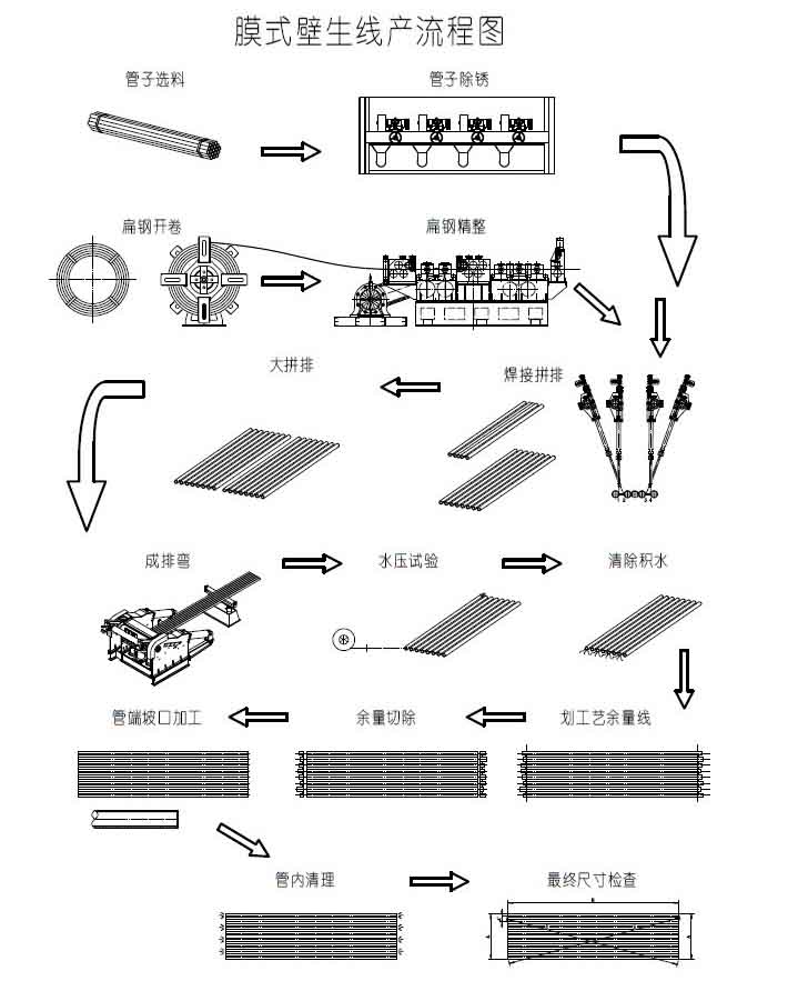
1) The first steps are i) Tubes are protected against rust and corrosion by a protective layer, this prohibits welding and requires them to be "cleaned" by either polishing or sand blasting. ii) Fin bars are required to be calibrated or sized to attain the desired consistency in a panel's final dimension.
2) The polished tube and fin bar then enters the panel welding machine to be joint by welding.
An example of the typical sequence of welding a 10 tubes membrane panel.
i) Pairs are joint and accummulated. It's essential to note: a) Always maximize the 4 torches when possible for maximum efficiency. b) To minimize the change in machine setting.
Step One
- Pairs are joint in this manner O-OO-O utilizing all 4 torches of the welder
- Accummucate multiples of O-O
Step Two
- With the completed pairs O-O, take 3 pairs and joint in becoming 6 as seen here O-O-O-O-O-O still utilizing all 4 torches of the welder
Step Three
- With the completed 6 tubes panel O-O-O-O-O-O, joint to it 2 completed pairs from step one. Still, we are utilizing all 4 torches of the welder
- O-O-O-O-O-O-O-O-O-O We now have a 10 tubes panel.
You should always remember!!! To avoid distortion, it's important to maintain a balanced heat input. To achieve this, firstly we maintain all 4 torches to have an equal input current and voltage setting, secondly we always weld at a position that's equal distance apart.
8 Tubes panel
You are probably asking about a 8 tube panel. So here's how we would do it.
Complete Step one and Step two of the above instruction.
What's different is (Remember equal distance apart), now for Step three of a 8 tube panel.
Here we have it O-O-O-O-O-O-O-O, instead of a pair from Step one, we placed a single tube and fin bar onto both the outer ends of the 6 tubes panel.
Design of membrane panel production line
The question is how much do you need to produce? From experience, a single panel welder machine with 4 torches could run over 1000 meters of weld on an 8 hour shift. A new user could find themselves acheving only 500 meters, and this number grows as the operator gains confidence over time.
Big boiler manufacturers could have up to 10 membrane panel welding machines.
So back to you, how much work do you have? Contact us for a solution.
How do we position a fin bar during the welding process
This is a question I get a lot, let us discuss this a little.
There are mainly 2 methods commonly seen or used in the industry. Please refer to the picture below:
Method 1
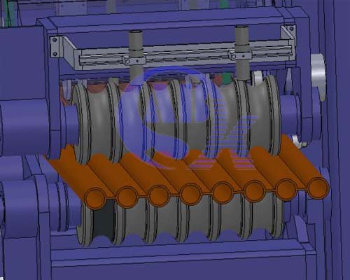
There are typically 2 sets of the above dies/mould installed at the front and back to hold into position the tube and fin bar. This would place the fin bar in the exact desired position during the welding process. However, every change of tube diameter, fin bar width, fin bar thickness would require an extensive replacement/change of the dies. This can be a tideous and time consuming process, often very expensive. Perhaps for manufacturers of a fixed design, without any custom orders or design changes could they not be required to change such dies.
Method 2
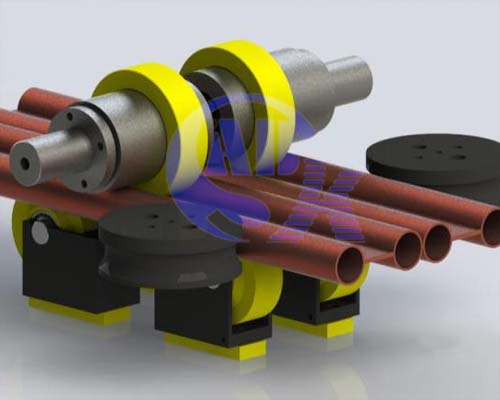
This is our way. The parts in yellow are dies and can be removed and replaced. The fin bar is supported into position by 2 sets of wheels at the bottom, and a ring on the top.
- The bottom rectangular piece (a shim plate- in yellow) adjusts the desired height to bring the fin bar into
the correct position from the bottom.
- The top ring (in yellow) slides into the roller clamp, can be easily obtained by machining. It positions the fin bar from the top.
- The bottom roller wheel (in yellow) changes when there is change in fin bar width.
You can afford to have different sizes in store, catering to different tube diameters, fin bar width and thickness. A complete set would cost just a few hundred dollars.
